You are here
ASIC Synthesis
Submitted by gc on Mon, 02/18/2013 - 04:54
RTL Synthesis involves three major steps:
- Transition from RTL description into gates and flip-flops
- Optimization of logic, and
- Placement and routing of optimized netlist.
Most of the intelligence resides in optimization stage but modern synthesis tools apply many smart techniques while converting RTL description into gates in order to reduce number of gates in the design.

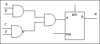
Figure 1: RTL to gate level netlist.
Quality Metrics for ASIC Synthesis
The technology library provided by fabrication house contains basic components like sequential gates : AND, OR, NOT, NAND, NOR, XOR, BUFFER, and sequential elements like latches, flip-flops and memories. Information about cell characteristics include cell delay and area. There are three major quality metrics: area, time and power. Designer's quality metric for an IC is driven by specific application.
1. Area: With shrinking system size ASIC should be able to accommodate maximum functionality in minimum area. Designer can specify area constraint and synthesis tool will optimize for minimum area. Area can be optimized by having lesser number of cells and by replacing multiple cells with single cell that includes both functionality.
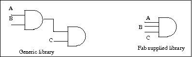
Figure 2: area optimization
2. Timing: Designer specifies maximum delay between primary input and primary output. This is taken as maximum delay across any critical path. There are three types of critical paths:
2.1 Path between a primary input and primary output.
2.2 Path from any primary input to a register.
2.3 Path from a register to a primary output.
2.4 Path from a register to another register.
3. Power: Development of hand-held devices has led to reduction of battery size and hence low power consuming systems. Low power consumption has become a big requirement for lot of designers.
Other Design rule constraints:
- Maximum fanout for a logic element.
- Maximum capacitance
- slew limit - slope of signal from 20% of target to 80% of target.
RTL to FSM to Gates
First step in synthesis process is to convert a given RTL into a finite state machine. Many transformations can be applied to finite state machine in order to reduce number of states.
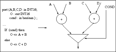
Figure 2: RTL to FSM(or graph)
Some of the common transformations applied to FSM are constant propagation, gate merging, dead code elimination, arithmetic merging. Next step is to generate hardware.
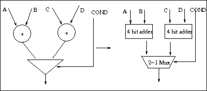
Figure 3: FSM(graph) to Gates.
Gate Level Logic Optimization
There are broadly two types of optimizations : Technology independent optimizations and Technology dependent optimization Technology dependent optimizations are carried out once netlist has been mapped into technology cells provided by fabrication house.
Timing and area constraints are provided by the designer. Slack is defined as difference between the expected arrival time and actual arrival time of signal at a particular output port. Slack is calculated for input to output paths. The aim of timing optimization is to reduce slack on critical paths.
Optimizations to reduce area include following :
- Constant propagation: Boolean minimization may lead to dissolution of certain section of code into constants. Such constants should be propagated at this stage in order to reduce gate count and area.
- Eliminate redundant logic: For example a + ab should be replaced by a.
- 2-level SOP optimization: converting all boolean logic to 2 level sum-of-products produces very fast designs but increases area. For example (a + b) ( c + d) = ac + bc + ad + bd
Some optimizations to improve timing are as follows:
1. Restructuring: If arrival times of signals at various input gates are known, they can be re-arranged to obtain better timing delay.
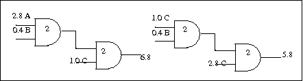
Figure 4: Reauthorization to improve timing.
2. Buffer insertion to improve timing along critical path. Replacing cell with a cell of higher drive strength can improve delay along critical path.
3. Pin assignment can be changed to match the late arriving input pin with pin having faster propagation delay to output.
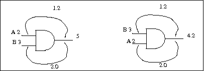
Figure 5: pin swapping to reduce delay.
4. False path removal. Netlist may contain false paths which are not visible in hardware description. It is important to remove these false paths in order to get accurate timing numbers and avoid wasting time in optimizing paths that are never sensitized.
Area Reclamation
Certain timing optimizations might lead to area escalation. Area Reclamation algorithms try to reclaim area which does not affect timing on critical paths.
- Downsizing the gates which contain extra pins.
- Buffers which were inserted to reach fanout constraint and are unnecessary are removed.
- Declone the cell instances which were cloned for decreasing number of fanouts.
Read on Kindle
Please consider leaving us a review on Amazon if you like it.
Wireless Networking: Introduction to Bluetooth and WiFi
